Code No. C145D: Wiring harness or coupling coil open circuit failure
|
| caution |
If there is any problem in the CAN bus lines, an incorrect diagnosis code may be set. Prior to this diagnosis, always diagnose the CAN bus lines.
|
|
OPERATION
If the current flowing in the electronic control coupling solenoid coil is smaller than the command value from 4WD-ECU, the system is deactivated.
DIAGNOSIS CODE SET CONDITIONS
If the following conditions are met when the system is activated, 4WD-ECU switches the control from 4WD to 2WD, flashes the 4WD/LOCK indicators alternately, and sets the diagnosis code No. C145D.
- Sets the specified current command value to the electronic control coupling solenoid
- Drive current value of the electronic control coupling solenoid: Deviated below from the normal current range
PROBABLE CAUSES
Current trouble
- Open circuit inside the electronic control coupling solenoid
- Damaged wiring harness and connectors
- Open circuit between 4WD-ECU and the electronic control coupling solenoid
- 4WD-ECU internal error
Past trouble
- Intermittent wiring harness or connector failure
| note |
For diagnosis procedures, refer to "How to treat past trouble" (Refer to GROUP 00, How to Treat Past Trouble  ). ).
|
- Intermittent electronic control coupling failure (solenoid failure)
|
|
STEP 1. M.U.T.-III CAN bus diagnostics
|
|
|
Use M.U.T.-III to diagnose the CAN bus lines.
|
|
|
Q.
Is the check result normal?
|
|
|
 Go to Step 3. Go to Step 3.
|
|
|
|
|
|
 Repair the CAN bus line (Refer to GROUP 54C - Troubleshooting ). On completion, go to Step 2. Repair the CAN bus line (Refer to GROUP 54C - Troubleshooting ). On completion, go to Step 2.
|
|
|
|
|
|
STEP 2. Check whether the diagnosis code is reset after repairing the CAN bus line.
|
|
|
(1)Erase the diagnosis code.
|
|
|
(2)Turn the ignition switch from the LOCK (OFF) position to the ON position and hold there for 2 seconds.
|
|
|
(3)Fully depress the accelerator pedal, and maintain its position for 2 seconds.
| note |
The coupling coil electronic control is also based on the accelerator pedal opening degree, thus the signal is sent to the ECU.
|
|
|
|
(4)Check if the diagnosis code is set.
|
|
|
Q.
Is the diagnosis code No. C145D set?
|
|
|
Go to Step 3.
|
|
|
|
|
|
This diagnosis is complete.
|
|
|
|
|
|
STEP 3. M.U.T.-III data list
|
|
|
Check the following service data (Refer to ).
|
|
|
- Item 04: Desired current of coupling
- Item 05: Monitored current of coupling
|
|
|
Q.
Is the check result normal?
|
|
|
Go to Step 10.
|
|
|
|
|
|
Go to Step 4.
|
|
|
|
|
|
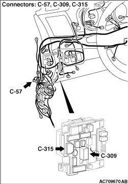
STEP 4. Check the following connector:
|
|
|
Check the connectors below for improper engagement, terminal damage or terminal drawn in the connector case.
|
|
|
- C-57 4WD-ECU connector
- D-39 intermediate connector
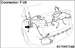
- F-26 electronic control coupling solenoid connector
- C-27 intermediate connector
|
|
|
Q.
Are the connectors and terminals in good condition?
|
|
|
Go to Step 5.
|
|
|
|
|
|
Repair the connector(s) or terminal(s). Then go to Step 11.
|
|
|
|
|
|
STEP 5. Wiring harness check
|
|
|
Check the wiring harness between the C-57 4WD-ECU connector and the F-26 electronic control coupling solenoid connector, and the wiring harness between the F-26 electronic control coupling solenoid connector and the F-26-1 electronic control coupling solenoid side connector for damage or other problem.
|
|
|
Q.
Is the wiring harness in good condition?
|
|
|
Go to Step 6.
|
|
|
|
|
|
Repair damage or other problem in the wiring harness. Then go to Step 11.
|
|
|
|
|
|
STEP 6. Resistance measurement between electronic control coupling solenoid connector (coupling side) terminals
|
|
|
Disconnect the F-26-1 connector, and measure the resistance value between the connector terminals on the electronic control coupling side.
|
|
|
Standard value: 2.2 - 4.0 Ω
|
|
|
Q.
Is the measured resistance value within the standard value range?
|
|
|
Go to Step 7.
|
|
|
|
|
|
Replace the electronic control coupling (Refer to ). Then go to Step 11.
|
|
|
|
|
|
STEP 7. Voltage measurement at the 4WD-ECU connector
|
|
|
(1)Disconnect the C-57 4WD-ECU connector.
|
|
|
(2)Measure the voltage between the C-57 wiring harness side connector terminals No.3, No.4 (ignition switch "ON") and the body earth.
OK: System voltage
|
|
|
Q.
Is the check result normal?
|
|
|
Go to Step 8.
|
|
|
|
|
|
Go to Step 9.
|
|
|
|
|
|
STEP 8. Wiring harness check
|
|
|
Check the wiring harness between the C-57 4WD-ECU connector (terminal No.10) and the body earth for damage or other problem.
|
|
|
Q.
Is the wiring harness in good condition?
|
|
|
Go to Step 10.
|
|
|
|
|
|
Repair the wiring harness. Then go to Step 11.
|
|
|
|
|
|
STEP 9. Wiring harness check
|
|
|
| note |
Prior to the wiring harness inspection, check the C-309 and C-315 ETACS-ECU connectors, and repair if necessary.
|
|
|
|
Check the wiring harness between the C-57 4WD-ECU connector (terminal No.3) and the fusible link No. 34, and the wiring harness between the C-57 4WD-ECU connector [terminal No.4 (ignition switch "ON")] and the fusible link No. 34 for damage or other problem.
|
|
|
Q.
Is the wiring harness in good condition?
|
|
|
Go to Step 10.
|
|
|
|
|
|
Repair the wiring harness. Then go to Step 11.
|
|
|
|
|
|
STEP 10. Check whether the diagnosis code is reset.
|
|
|
(1)Erase the diagnosis code.
|
|
|
(2)Turn the ignition switch from the LOCK (OFF) position to the ON position and hold there for 2 seconds.
|
|
|
(3)Fully depress the accelerator pedal, and maintain its position for 2 seconds.
| note |
The coupling coil electronic control is also based on the accelerator pedal opening degree, thus the signal is sent to the ECU.
|
|
|
|
(4)Check if the diagnosis code is set.
|
|
|
Q.
Is the diagnosis code No. C145D set?
|
|
|
Replace 4WD-ECU (Refer to ). Then go to Step 11
.
|
|
|
|
|
|
The trouble can be an intermittent malfunction (Refer to GROUP 00 - How to Cope with Intermittent Malfunction ).
|
|
|
|
|
|
STEP 11. Check whether the diagnosis code is reset.
|
|
|
(1)Erase the diagnosis code.
|
|
|
(2)Turn the ignition switch from the LOCK (OFF) position to the ON position and hold there for 2 seconds.
|
|
|
(3)Fully depress the accelerator pedal, and maintain its position for 2 seconds.
| note |
The coupling coil electronic control is also based on the accelerator pedal opening degree, thus the signal is sent to the ECU.
|
|
|
|
(4)Check if the diagnosis code is set.
|
|
|
Q.
Is the diagnosis code No. C145D set?
|
|
|
Diagnose again from Step 1.
|
|
|
|
|
|
This diagnosis is complete.
|
|
|
|
 faq.Lancer-Club.ru
)
)
)